

.jpg")
EC-1800 Conductivity Meter
零售价
市场价
The meter can be adapted to a variety of conductivity electrodes: 0.01, 0.02, 0.1, 1.0, 10.0cm-1 conductivity electrodes, measuring range from 18.25 MΩ(0.05 us) to 100 mS (temperature compensation using NTC10K, can achieve 0-120℃ temperature measurement);
The instrument is widely used in water treatment equipment, environmental engineering, pharmaceutical, electronics, chemical, agricultural planting, aquaculture, scientific research institutes, electroplating, metallurgical manufacturing, machining and other industries.
重量
库存
隐藏域元素占位
EC-1800 Conductivity Meter
The meter can be adapted to a variety of conductivity electrodes: 0.01, 0.02, 0.1, 1.0, 10.0cm-1 conductivity electrodes, measuring range from 18.25 MΩ(0.05 us) to 100 mS (temperature compensation using NTC10K, can achieve 0-120℃ temperature measurement);
The instrument is widely used in water treatment equipment, environmental engineering, pharmaceutical, electronics, chemical, agricultural planting, aquaculture, scientific research institutes, electroplating, metallurgical manufacturing, machining and other industries.
Category:
Conductivity Transmitter
- Product Description
-
■ Overview
The EC-1800 is an intelligent upgrade of DJK-110 industrial conductivity/TDS meter, designed for continuous monitoring in:
✔ Scientific research ✔ Chemical/pharmaceutical ✔ Environmental protection
✔ Metallurgy ✔ Papermaking ✔ Food/beverage ✔ Water supply
Dual Power Options:- ● EC-1800A: 220V AC (IEC 61140 compliant)
- ● EC-1800B: Safety low-voltage 24V AC/DC (SELV/PELV certified)
Key Features:
- ● Bilingual UI (CN/EN switchable)
- ● Conductivity/TDS + temperature measurement with dual relay output control
- ● Adjustable temp. compensation (0-10%) & TDS conversion factors
- ● 4-20mA isolated output (300Ω max loop resistance)
- ● Audible alarm with on/off setting
- ● Programmable LCD backlight (auto-off available)
- ● EMI-resistant design with industrial-grade CPU
- ● One-touch factory reset & password protection
■ Technical Specifications
Accuracy: ±1% FS
Stability: ±1% FS/24h
Electrodes: 1.0 ABS platinum-black / 316L stainless steelStandard Range
Extended Range
Measurement Range Measurement Range 0.1 electrode 0.2-2000 μS/cm-1 0.1 electrode 2-2000 μS/cm-1 1.0 electrode 2-20000 μS/cm-1 1.0 electrode 20μS-20.0 mS/cm-1 10.0 electrode 20μS-20.0 mS/cm-1 10.0 electrode 20μS-200.0 mS/cm-1 - Cell Constant: 0.1/1.0/10.0 cm⁻¹
- Electrode Thread: 1/2" NPT
- Electrode Cable Length: 4.5m for ABS probe; 10m for 316SS probe(Customizable)
- Temp. compensation: Auto mode (PT1K or NTC10K) reference at 25℃
- Medium Temp range: normal temp: 0-60℃, high temp: 0-120℃
- Medium Pressure: 0~0.5MPa
- Meter Display: 128×64 LCD Screen
- Outputs:
Controlling: Dual relay alarms (5A/250V AC contacts)
Signal: 4-20mA analog output (Isolated), RS485 is optional- Power Supply:
Standard: AC 220V
Optional: AC 110V or DC24V- Power Consumption: ≤3W
- Environmental Conditions:
Operating Temperature: 0~60℃
Humidity: ≤85% RH- Dimensions:
Housing: 96×96×110mm (H×W×D)
Panel Hole: 92×92mm (H×W)■ Installation
1.Insert controller through panel cutout (92×92mm)
2.Secure with included brackets
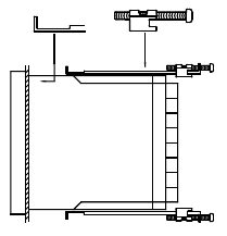
Figure 1 Fixed support installation
■ Wiring connection diagram

Figure 2 Rear terminals diagram
■ Connection notes
1. R (红):Temperature (NTC10K)
2. Y (黄):Conductivity
3. B (黑):Temperature(NTC10K)
4. W (白):Conductivity
5. 485A:RS485 communication port
6. 485B:RS485 communication port
7. mA+: 4~20mA output +
8. mA-: 4~20mA output -
9. LO: low limit alarm
10. HI: high limit alarm
11. NC:undefined
12. NC:undefined
13. N:220V power connection
14. L:220V power connection■ Electrode Installation
1)Electrode constant selection:
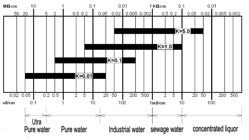
Figure 3 Electrode constant selection
2)Electrode installation diagram
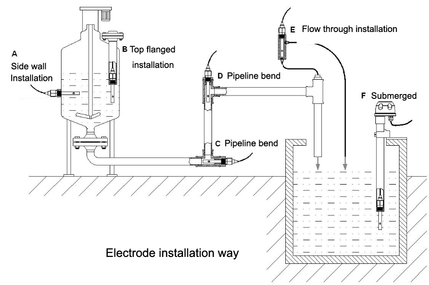
Figure 5 Electrode installation diagram
Issue
Possible Cause
Troubleshooting Tips
No display with powered onA: Double check on the power supply
B: Instrument failure
A: Check the presence of voltage between the instrument power terminals.
B: Contact aftersales personnel.Unstable displayA: The wiring of the conductivity cell is wrong.
B: Bubbles in the pipeline.C: Unstable water quality.A Check and reconnect per the wiring diagram.
B: Rectify the pipeline or choose another measurement pointC: Change a more stable water source.Large discrepancy in readings
A: The constant is not set correctly.
B: The conductivity probe needs to be changed.C: Measurement point is not perfect.D: Wrong installation of the conductivity cellA: Reset the conductivity constant in the meter.
B: Replace the conductivity cell with a new one or recalibrate the current cell.C: Install the conductivity cell in accordance with above instructions.D: Same as C.Large deviation in measurement data
A: Meter of conductivity cell failure.B: Incorrect instrument setting.A: for conductivity cell failure, check whether the resistance between the red line and the white line of the conductivity cell is about 1 MΩ, and that between yellow line and white line is 10KΩ, and the conductivity of the battery between white line and black line insulation >100 MΩ@100V. If above conductions all correct, it means the conductivity cell is normal with no problem.B: Instrument failure, check whether the instrument’s parameter are all set correctly.Displays of the two points mA do not match.
A: Receiver migration error.
B: Not reaching 20mA.C: Improper sending setting.D: The sending of mA might be not matching.A: Reset the amount of receiving migration.
B: Loop resistance is too large, increasing the cable cross-sectional area.C: Reset the meter mA to indicate corresponding value.D: Connect the meter directly in series in the mA loop to verify the current value.
The High Accuracy Conductivity Meter is designed for precise and reliable conductivity measurement in industrial, laboratory, and water treatment applications. Featuring advanced sensor technology and a user-friendly interface, it delivers fast response and stable performance. The meter supports accurate monitoring of water quality, chemical solutions, and purification systems. With durable construction, automatic calibration, and low maintenance requirements, it is ideal for continuous testing environments.
Product Inquiry
If you have any questions or needs, please leave a message or contact us and we will reply you as soon as possible.

Shanghai ChiMay Tech ltd.
Address:
Block 8, No 8188, DaYe Road, Fengxian District, Shanghai, 201409, China
Telephone:
+86 13817226169
WhatsApp:
+86 13817226169
Email:
Subscribe to our newsletter
Want to stay up to date with news and updates about our product? Subscribe.